With the support of the University of Virginia’s Educational Innovation Award, we have developed Instructional Modules that accelerate material delivery and student learning in two introductory mechanics courses jointly offered by the
Civil Engineering and Mechanical and Aerospace Engineering Departments, namely CE/MAE 2300 (Statics) and CE/MAE 2310 (Strength of Materials). The two sets of modules are listed in the two tables below. They can be accessed by either clicking on the
appropriate buttons below or by navigating to the Statics and Strength of Materials tabs above.
Statics Modules
Strength of Materials Modules
#
Module Name
1
Force Vector (2D)
2
Force Vector (3D)
3
Force Vector Addition
4
Position Vector
5
Force Projection 1
6
Force Projection 2
7
Particle Equilibrium (2D)
8
Particle Equilibrium (3D)
9
Moment of a Force (2D)
10
Moment of a Force (3D)
11
Moment of a Force about an Axis
12
Couple Moment
13
Moving a Force to a Point
14
Moving a Force to a Point (Animation)
15
Reduction of a Distributed Loading
16
Open a Lid
17
Introduction to FBD
18
FBD of Beam
19
Equilibrium of Beams
20
Determinacy of Beams
21
Method of Joints
22
Method of Sections
23
Comprehensive Truss Problem
24
Internal Loadings in a Beam 1
25
Internal Loadings in a Beam 2
26
Friction
27
Moving Downward or Upward
28
Centroid of a Body
29
Fluid Pressure
30
Moment of Inertia
31
Moment of Inertia for Composite Areas
32
Product of Inertia
#
Module Name
1
Stress on an Oblique Plane
2
Stress at a Point
3
Internal Shear and Moment Diagram
4
Pin Diameter Determination
5
Strain
6
Mechanical Properties of Materials
7
Stress-Strain Relations
8
Tensile Test
9
Stress Superposition
10
Thermal Stress
11
Torsion
12
Shear Stress from Torque
13
Stress on Over-Constrained Bar
14
Bending
15
Shear Flow of a Section
16
Combined Loadings
17
Stress Transformation
18
Beam Deflection
Particle Equilibrium (2D)
The movement of a dot can be described by Newton's Second Law,
\begin{equation}
\sum _{k=1}^n
\buildrel{\rightharpoonup}\over{{F}_k} = \buildrel{\rightharpoonup}\over{ma}
\end{equation}
In Cartesian coordinate system x-y, it can be written as,
\begin{equation}
\sum _{k=1}^n {F}_k cos\theta_{k}\buildrel{\rightharpoonup}\over{i} + {F}_k sin\theta_{k}\buildrel{\rightharpoonup}\over{j} = ma_{x}\buildrel{\rightharpoonup}\over{i} + ma_{x}\buildrel{\rightharpoonup}\over{j}
\end{equation}
or separately as,
\begin{equation}
\sum _{k=1}^n {F}_k cos\theta_{k} = ma_{x}, \sum _{k=1}^n {F}_k sin\theta_{k} = ma_{y}
\end{equation}
where $F_{k}$ is the magnitude of the $k^{th}$ force, $\Theta_{k}$ is the angle between the direction of the $k^{th}$ force and coordinate axis or x axis, m is the mass of the dot and $a_{x}$, $a_{y}$ are the acceleration projection in x, y direction.
$\buildrel{\rightharpoonup}\over{F} \,=\, F_x\buildrel{\rightharpoonup}\over{i}+F_y \buildrel{\rightharpoonup}\over{j} = \sqrt{F_x^2+F_y^2} (\frac{F_x }{\sqrt{F_x^2+F_y^2}}\buildrel{\rightharpoonup}\over{i}+\frac{F_y
}{\sqrt{F_x^2+F_y^2}}\buildrel{\rightharpoonup}\over{j})=\buildrel{\rightharpoonup}\over{\|F\|}(\frac{F_x}{\buildrel{\rightharpoonup}\over{\|F\|}}\buildrel{\rightharpoonup}\over{i}+\frac{F_y}{\buildrel{\rightharpoonup}\over{\|F\|}}\buildrel{\rightharpoonup}\over{j})$
In the following example, we have three forces $F_{1}$, $F_{2}$, and $F_{3}$. Thus we have
\begin{equation}
{F}_1 cos\theta_{1} + {F}_2 cos\theta_{2} + {F}_3 cos\theta_{3} = ma_{x}
\end{equation}
\begin{equation}
{F}_1 sin\theta_{1} + {F}_2 sin\theta_{2} + {F}_3 sin\theta_{3} = ma_{y}
\end{equation}
By setting the magnitude and direction of each forces, we can see the movement of the dot. If forces
are set properly, the dot can remain in static equilibrium and thus will not move.
Internal Loadings in a Beam 1
To design a structural or mechanical member it is necessary to know the loading acting within the
member in order to be sure the material can resist this loading. Internal loadings can be determined
by using the method of sections. To illustrate this method, this module will show you how to determine
the internal loadings.
$\textbf{Normal force}$: The force component that acts perpendicular to the cross section.
$\textbf{Shear force}$: The force component that is tangent to the cross section.
$\textbf{Bending moment}$: The couple moment within the section.
The force components prevent the relative translation between the two segments, and the couple moment
prevents the relative rotation. According to Newton's third law, these loadings must act in opposite
directions on each segment.
Friction
The module below shows how the friction changes on a slope.
When a block is statistically placed on a slope with inclined angle $\theta$ and coefficient of
friction $\mu$, the friction provided by the slope is a static frictional force; as $\theta$ increases
gradually and exceeds the critical value, $\theta_{0}$ = Arctan($\mu$), the statistic balance is
broken and the block begins to move, with the static frictional force changed to kinetic frictional
force. While in the original balance state, changing the mass of the block, m, cannot break the
balance.
Module below shows these ideas where $\mu$ and m are variable and $\theta$ can be increased
automatically to $\theta_{0}$. Play with these parameters to see how the FBD and balance change.
Fluid Pressure
According to Pascal's law, a fluid at rest creates a pressure p at a point that is the same in all
directions. The magnitude of p, measured as a force per unit area, depends on the specific mass
density $\rho$ of the fluid and the depth z of the point from the fluid surface. The relationship can
be expressed mathematically as
\begin{equation}
P = \rho gz
\end{equation}
Consider three types of submerged plate and calculate their resultant force, including the magnitude,
directions and acting point.
First type is flat plate with constant width, this is the simplest type. Since the plate is flat, all
the forces thus the resultant force will be perpendicular to the plate. The magnitude of pressure will
vary linearly w.r.t. its depth. Integrating the force directly, we can get the magnitude of resultant
force, which is equal to the pressure at the centroid times the plate area. Integrating the moment
w.r.t a reference point, and we can get the resultant moment thus determine the acting point of the
resultant force.
Second type is curved plate with constant width. Since the plate is curved, the forces direction will
vary in different point. Thus we need to decompose the force into x direction and y direction, and
then do the integration separately. Then integrate the moment w.r.t a reference point, and we can get
the resultant moment thus determine the acting point of the resultant force. For a curve like cylinder
surface, since every force will pass the axis, thus we know resultant force will also pass axis in
order to have a zero moment w.r.t axis, this brings some benefits for the further determination of
acting point of resultant force.
Third type is flat plate with variable width. The magnitude of resultant is relatively easy to
determine since it will perpendicular to the plate. Also, it will equal to the pressure at the
centroid times the plate area. Integrating the moment w.r.t a reference point, and we can get the
resultant moment thus determine the acting point of the resultant force.
For second type there is an easier way to determine its resultant by calculating the equivalent
loading. For details please see the textbook.
Force Vector (2D)
For 2D case, a force vector can be represented as,
\begin{equation}
\buildrel{\rightharpoonup}\over{F} = F_x\buildrel{\rightharpoonup}\over{i}+F_y
\buildrel{\rightharpoonup}\over{j} \,=\, \sqrt{F_x^2+F_y^2} (\frac{F_x
}{\sqrt{F_x^2+F_y^2}}\buildrel{\rightharpoonup}\over{i}+\frac{F_y
}{\sqrt{F_x^2+F_y^2}}\buildrel{\rightharpoonup}\over{j})=\buildrel{\rightharpoonup}\over{\|F\|}(\frac{F_x}{\buildrel{\rightharpoonup}\over{\|F\|}}\buildrel{\rightharpoonup}\over{i}+\frac{F_y}{\buildrel{\rightharpoonup}\over{\|F\|}}\buildrel{\rightharpoonup}\over{j})
\end{equation}
Note that $\cos\alpha = \frac{F_x}{\buildrel{\rightharpoonup}\over{\|F\|}}$ and $\cos\beta =
\frac{F_y}{\buildrel{\rightharpoonup}\over{\|F\|}}$ where $\alpha$ is the angle between the vector and
x-axis, $\beta$ is the angle
between the vector and y-axis. Thus we have,
\begin{equation}
\buildrel{\rightharpoonup}\over{F} =
\buildrel{\rightharpoonup}\over{\|F\|}(\cos\alpha\buildrel{\rightharpoonup}\over{i} +
\cos\beta\buildrel{\rightharpoonup}\over{j} =
\buildrel{\rightharpoonup}\over{\|F\|}\buildrel{\rightharpoonup}\over{u}
\end{equation}
Where $\buildrel{\rightharpoonup}\over{u} = (\cos\alpha\buildrel{\rightharpoonup}\over{i} +
\cos\beta\buildrel{\rightharpoonup}\over{j})$ is the unit vector.
Force Vector Addition
Experimental evidence has shown that a force is a vector quantity since it has a specified magnitude,
direction, and sense and it adds according to the parallelogram law.
Two common problems in statics involve either finding the
resultant force, knowing its components, or resolving a known force into two components. We will now
describe how each of these problems is solved using the parallelogram law.
Given two forces, $\buildrel{\rightharpoonup}\over{F_1}$ and $\buildrel{\rightharpoonup}\over{F_2}$,
we know their magnitudes $F_1$ and $F_2$ and directions $\theta_1$, $\theta_2$. The two forces
$\buildrel{\rightharpoonup}\over{F_1}$ and $\buildrel{\rightharpoonup}\over{F_2}$ can be added
together to form the resultant force $\buildrel{\rightharpoonup}\over{F_R}$ =
$\buildrel{\rightharpoonup}\over{F_1}$ +
$\buildrel{\rightharpoonup}\over{F_2}$. The adding process is shown below.
From this construction, we can apply the law of cosines or the law of sines to the triangle in order
to obtain the magnitude of the resultant force and its direction. We know that $\left| \theta _1 -
\theta _2\right|$ = $\alpha +
\beta = \pi - \gamma$, thus we have $\gamma = \pi$ - $\left| \theta _1 - \theta _2\right|$. Using law
of cosines we know the magnitude of resultant force will be
Once we get $\alpha$, $\beta$ we can get the magnitude direction $\theta$ by the geometry,
\begin{equation}
\theta = (\beta +\theta _1, \text{if} \,\,\, \theta _1<\theta _2), (\alpha +\theta _2, \text{if}
\,\,\, \theta _1>\theta _2) \\
\end{equation}
Thus we know the magnitude as well as direction of the resultant force
$\buildrel{\rightharpoonup}\over{F_R}$.
Force Vector (3D)
For 3D case, a force vector can be represented as
\begin{equation}
\buildrel{\rightharpoonup}\over{F} = F_x \buildrel{\rightharpoonup}\over{i} + F_y
\buildrel{\rightharpoonup}\over{j} + F_z \buildrel{\rightharpoonup}\over{k}
\end{equation}
\begin{equation}
\buildrel{\rightharpoonup}\over{F} = \sqrt{F_x^2+F_y^2+F_z^2} \,\,
(\frac{F_x}{\sqrt{F_x^2+F_y^2+F_z^2}}\buildrel{\rightharpoonup}\over{i} +
\frac{F_y}{\sqrt{F_x^2+F_y^2+F_z^2}}\buildrel{\rightharpoonup}\over{j} +
\frac{F_z}{\sqrt{F_x^2+F_y^2+F_z^2}}\buildrel{\rightharpoonup}\over{k})
\end{equation}
\begin{equation}
\buildrel{\rightharpoonup}\over{F} = \left\|\buildrel{\rightharpoonup}\over{F}\right\|
(\frac{F_x}{\left\|\buildrel{\rightharpoonup}\over{F}\right\|}\buildrel{\rightharpoonup}\over{i}+\frac{F_y}{\left\|\buildrel{\rightharpoonup}\over{F}\right\|}\buildrel{\rightharpoonup}\over{j}+
\frac{F_z}{\left\|\buildrel{\rightharpoonup}\over{F}\right\|}\buildrel{\rightharpoonup}\over{k})
\end{equation}
Note that $\cos\alpha = \frac{F_x}{\left\|\buildrel{\rightharpoonup}\over{F}\right\|}$, $\cos\beta =
\frac{F_y}{\left\|\buildrel{\rightharpoonup}\over{F}\right\|}$, $\cos\gamma =
\frac{F_z}{\left\|\buildrel{\rightharpoonup}\over{F}\right\|}$, where $\alpha$ is the angle between
the vector and x-axis, $\beta$ is the angle between the vector and y-axis, $\gamma$ is the angle
between the vector and z-axis,
they satisfy the relation $\cos^{2}\alpha + \cos^{2}\beta + \cos^{2}\gamma = 1$. Then we have
\begin{equation}
\buildrel{\rightharpoonup}\over{F} = \left\|\buildrel{\rightharpoonup}\over{F}\right\| (\cos^{2}\alpha
+ \cos^{2}\beta + \cos^{2}\gamma) =
\left\|\buildrel{\rightharpoonup}\over{F}\right\|\buildrel{\rightharpoonup}\over{u}
\end{equation}
Where $\buildrel{\rightharpoonup}\over{u}$ = ($\cos^{2}\alpha + \cos^{2}\beta + \cos^{2}\gamma$) is
the unit vector. By changing the magnitude and angles, we can get a different
$\buildrel{\rightharpoonup}\over{F}$. Alternatively,
we can use the components to control $\buildrel{\rightharpoonup}\over{F}$. Since we have
\begin{equation}
\buildrel{\rightharpoonup}\over{F} = F_x \buildrel{\rightharpoonup}\over{i} + F_y
\buildrel{\rightharpoonup}\over{j} + F_z \buildrel{\rightharpoonup}\over{k}
\end{equation}
By changing the components $F_x, F_y, F_z$ directly, we can also get a different
$\buildrel{\rightharpoonup}\over{F}$.
Position Vector
A position vector $\buildrel{\rightharpoonup}\over{r}$ is defined as a fixed vector which locates a
point in space relative to another point.
If we know the coordinate of a point, say A, as $x_a, y_a, z_a$, then the position vector from origin
point to A will be
\begin{equation}
r_a = x_a i + y_a j + z_a k
\end{equation}
Similarly, for point B with coordinate $x_b, y_b, z_b$, the position vector from origin point to B
will be
\begin{equation}
r_b = x_b i + y_b j + z_b k
\end{equation}
Thus, the position vector from point A to point B will be
\begin{equation}
r = r_b - r_a = (x_b - x_a) i + (y_b - y_a) j + (z_b - z_a) k
\end{equation}
As a matter of convention, we will sometimes refer to this vector with two subscripts to indicate from
and to the point where it is
directed. Thus, r can also be designated as $r_{ab}$.
Force Projection 1
Once we get a force, including its direction and magnitude, we can know its projection on a certain
given line.
In the following example, we have two lines which passes points A, B and points A, C separately, thus
we can define them as line AB and line AC. The direction of force is along line AC and starts from
point A, also its magnitude
can be set. Thus, we can show the projection of force $F_{AC}$ on line AB. The magnitude of projection
is given by
\begin{equation}
F_{AB} = F_{AC} \,\, cos\theta
\end{equation}
Where $\theta$ is the angle between line AB and line AC.
Moment of a Force (2D)
The moment of a force $\buildrel{\rightharpoonup}\over{F}$ about point O, or actually about the moment
axis passing through O and perpendicular to the plane containing O and
$\buildrel{\rightharpoonup}\over{F}$, can be expressed
using the vector cross product, namely $\buildrel{\rightharpoonup}\over{M_O}$ =
$\buildrel{\rightharpoonup}\over{r}$ x $\buildrel{\rightharpoonup}\over{F}$. Here
$\buildrel{\rightharpoonup}\over{r}$ represents a position vector
directed from O to any point on the line of action of $\buildrel{\rightharpoonup}\over{F}$.
For a beam with unbalanced moment $\buildrel{\rightharpoonup}\over{M_O}$, the equation of motion is
described by $\buildrel{\rightharpoonup}\over{M_O}$ = $I_O
\buildrel{\rightharpoonup}\over{\ddot\theta}$, where
$\buildrel{\rightharpoonup}\over{\ddot\theta}$ is the angular acceleration, $I_O$ is the moment of
inertia with respect to O. If the beam is constrained to be rotate within certain plane, the equation
of motion is simplified as
$M_O$ = $I_O \ddot\theta$.So we see, in order to keep the beam in static, we need to make the $M_O$ to
zero.
For the following problem, we have two forces $\buildrel{\rightharpoonup}\over{F_1}$,
$\buildrel{\rightharpoonup}\over{F_2}$, with their magnitudes, directions and acting positions to be
set. Both of them produce the moment with
respect to hinge, and the resultant may cause the moment to rotate with respect to hinge. We can see
the rotation once we set unbalanced moment of these two forces. Also, we can see that the beam will
keep in static once the
resultant moment is zero.
Moment of a Force (3D)
The moment of a force $\buildrel{\rightharpoonup}\over{F}$ about point O, or actually about the moment
axis passing through O and perpendicular to the plane containing O and
$\buildrel{\rightharpoonup}\over{F}$, can be expressed
using the vector cross product, namely $\buildrel{\rightharpoonup}\over{M_O}$ =
$\buildrel{\rightharpoonup}\over{r}$ x $\buildrel{\rightharpoonup}\over{F}$. Here
$\buildrel{\rightharpoonup}\over{r}$ represents a position vector
directed from O to any point on the line of action of $\buildrel{\rightharpoonup}\over{F}$.
For an object with unbalanced moment $\buildrel{\rightharpoonup}\over{M_O}$, the equation of motion is
described by $\buildrel{\rightharpoonup}\over{M_O}$ = $I_O
\buildrel{\rightharpoonup}\over{\ddot\theta}$, where
$\buildrel{\rightharpoonup}\over{\ddot\theta}$ is the angular acceleration, $I_O$ is the moment of
inertia with respect to O.
For the following problem, we will set the position of O and the position of a sphere with the center
at C. We have a force $\buildrel{\rightharpoonup}\over{F}$, with the magnitude, directions and acting
positions at C. The force
will produce the moment with respect to point O, and the moment may cause the sphere to rotate with
respect to O. We can see the rotation once the moment is non-zero. Also, we can see that the sphere
will keep in static once the
moment is zero.
Moment of a Force about an Axis
In 3D case, the moment of a Force about a Specified Axis is
\begin{equation}
\buildrel{\rightharpoonup}\over{M_a} \,\,=\,\, \buildrel{\rightharpoonup}\over{u_a} \bullet \,\,
(\buildrel{\rightharpoonup}\over{r} X \buildrel{\rightharpoonup}\over{F})
\end{equation}
\begin{equation}
\buildrel{\rightharpoonup}\over{M_a} \,\,= \begin{vmatrix}
\buildrel{\rightharpoonup}\over{u_{a_{x}}} & \buildrel{\rightharpoonup}\over{u_{a_{y}}} &
\buildrel{\rightharpoonup}\over{u_{a_{z}}} \\
r_x & r_y & r_z \\
F_x & F_y & F_z
\end{vmatrix}
\end{equation}
\begin{equation}
\buildrel{\rightharpoonup}\over{M_a} \,\,=\,\, \buildrel{\rightharpoonup}\over{u_{a_{x}}}(r_y F_z -
r_z F_y) - \buildrel{\rightharpoonup}\over{u_{a_{y}}}(r_x F_z - r_z F_x) +
\buildrel{\rightharpoonup}\over{u_{a_{z}}}(r_x F_y - r_y
F_x)
\end{equation}
where $u_{a_{x}}, u_{a_{y}}, u_{a_{z}}$ represent the x, y, z components of the unit vector defining
the direction of the a axis. $r_{x}, r_{y}, r_{z}$ represent the x, y, z compoments of the position
vector extended from any point
O on the a axis to any point A on the line of action of the force. $F_{x}, F_{y}, F_{z}$ represent the
x, y, z components of the force vector.
Couple Moment
A couple is defined as two parallel forces that have the same magnitude, but opposite directions, and
are separated by a perpendicular distance d. Since the resultant force is zero, the only effect of a
couple is to produce an
actual rotation, or if no movement is possible, there is a tendency of rotation in a specified
direction.
The moment produced by a couple is called a couple moment. We can determine its value by finding the
sum of the moments of both couple forces about any arbitrary point. The magnitude of moment can be
defined as
\begin{equation}
M = Fd
\end{equation}
Where F is the magnitude of one of the forces and d is the perpendicular distance or moment arm
between the forces.
In the following example, a couple act on a gear, in which we can define the acting point of each
force, as well as the magnitude and direction of the force, and see the effect of such moment on the
gear.
Moving a Force to a Point
Sometimes it is convenient to reduce a system of forces and couple moments acting on a body to a
simpler form by replacing it with an equivalent system, consisting of a single resultant force acting
at a specific point and a
resultant couple moment. A system is equivalent if the external effects it produces on a body are the
same as those caused by the original force and couple moment system. In this context, the external
effects of a system refer to
the translating and rotating motion of the body if the body is free to move, or it refers to the
reactive forces at the supports if the body is held fixed.
The key point of such reduction is how to move a force to a given point equivalently. The following
case shows the procedure of such moving. $\buildrel{\rightharpoonup}\over{F_{A}}$ is applied at point
A, and we want to move it to
point B without disturbing the overall equilibrium. So, we add two forces at point A, they are both
parallel with $\buildrel{\rightharpoonup}\over{F_{A}}$ and have the same magnitude of
$\buildrel{\rightharpoonup}\over{F_{A}}$, but
on has the same direction as $\buildrel{\rightharpoonup}\over{F_{A}}$ and other has opposite direction
as $\buildrel{\rightharpoonup}\over{F_{A}}$. Here, we denote them as
$\buildrel{\rightharpoonup}\over{F_{B+}}$ and
$\buildrel{\rightharpoonup}\over{F_{B-}}$ separately. Now, since
$\buildrel{\rightharpoonup}\over{F_{A}}$ and $\buildrel{\rightharpoonup}\over{F_{B-}}$ make up a
couple moment $\buildrel{\rightharpoonup}\over{M}$, they can be
replaced with $\buildrel{\rightharpoonup}\over{M}$. Thus, the system can be replaced by a force acting
at B which is $\buildrel{\rightharpoonup}\over{F_{B+}}$, together with a couple moment
$\buildrel{\rightharpoonup}\over{M}$
which is a free vector. $\buildrel{\rightharpoonup}\over{F_{B+}}$ and
$\buildrel{\rightharpoonup}\over{M}$ are determined by
\begin{equation}
\buildrel{\rightharpoonup}\over{F_{B+}} \,\,=\,\, \buildrel{\rightharpoonup}\over{F_{A}},\,\,
\buildrel{\rightharpoonup}\over{M} = (\buildrel{\rightharpoonup}\over{r_{A}} -
\buildrel{\rightharpoonup}\over{r_{B}}) \,\times
\buildrel{\rightharpoonup}\over{F_{A}}
\end{equation}
By doing this, we can move a force to any given point without disturbing the overall equilibrium since
the total force and the total moment produced by the force about any point remain the same. Suppose we
have several forces
acting on several points, we can use same process to move these forces to an given point equivalently,
and then get one resultant force and one resultant couple moment for all the forces acting at this
point as well as those couple
moments, thus simplifying the system.
Moving a Force to a Point (Animation)
This modulus shows the animation of "Moving a Force to Another Point", aiming to give a more clear
view about how the moment change during the moving process.
In the following modulus, initially we have a force $\buildrel{\rightharpoonup}\over{F}$ acting on
point A, thus the moment it produces w.r.t. point B will be $\buildrel{\rightharpoonup}\over{M_{BO}}$
=
($\buildrel{\rightharpoonup}\over{r_{A}}$ - $\buildrel{\rightharpoonup}\over{r_{B}}$) x
$\buildrel{\rightharpoonup}\over{F}$.
When we move $\buildrel{\rightharpoonup}\over{F}$ from point A to point B along the line AB, say, we
reach a point C locates at line AB. Since the magnitude of ($\buildrel{\rightharpoonup}\over{r_{C}}$ -
$\buildrel{\rightharpoonup}\over{r_{B}}$) is less than that of
($\buildrel{\rightharpoonup}\over{r_{A}}$ - $\buildrel{\rightharpoonup}\over{r_{B}}$) while has the
same direction, thus magnitude of
$\buildrel{\rightharpoonup}\over{M_B}$ decrease while its direction remains the same, we have
$\buildrel{\rightharpoonup}\over{M_{B}}$ = ($\buildrel{\rightharpoonup}\over{r_{C}}$ -
$\buildrel{\rightharpoonup}\over{r_{B}}$) x
$\buildrel{\rightharpoonup}\over{F}$. Meanwhile, the couple moment at C increases, from 0 (at initial
point A) to the $\buildrel{\rightharpoonup}\over{M_{C}}$ = ($\buildrel{\rightharpoonup}\over{r_{A}}$ -
$\buildrel{\rightharpoonup}\over{r_{C}}$) x $\buildrel{\rightharpoonup}\over{F}$ (at point C), the
value of which can be gotten through the process in the previous modulus, i.e. "Moving a Force to
Another Point". When
$\buildrel{\rightharpoonup}\over{F}$ reaches point B, or we can say C coincide with B, then the couple
moment becomes $\buildrel{\rightharpoonup}\over{M_{C}}$ = ($\buildrel{\rightharpoonup}\over{r_{A}}$ -
$\buildrel{\rightharpoonup}\over{r_{B}}$) x $\buildrel{\rightharpoonup}\over{F}$, which is the same
with the $\buildrel{\rightharpoonup}\over{M_{BO}}$.
Through this moving process, we can clearly see how the couple moment
$\buildrel{\rightharpoonup}\over{M_{C}}$ increases and finally equals to
$\buildrel{\rightharpoonup}\over{M_{BO}}$
Reduction of a Distributed Loading
A body subjected to loading distributed over its surface can be simplified to one point force,
$\buildrel{\rightharpoonup}\over{F_{R}}$. The magnitude of $\buildrel{\rightharpoonup}\over{F_{R}}$ is
equivalent to the sum of all the forces in the system. Integration is used to determine the
differential area dA under the loading curve for the entire length L.
\begin{equation}
\buildrel{\rightharpoonup}\over{F_{R}} \,\,\,= \int w(x)\, dx\,\, from \,\, [x_{1} \,\,to\,\, x_{2}]
\end{equation}
The location x-bar of the line of action of $\buildrel{\rightharpoonup}\over{F_{R}}$ can be determined
by equating the moments of the force resultant and the parallel force distribution about point O (the
y axis).
Therefore, x-bar $= \int xw(x)\, dx\,\, / \int w(x)\, dx\,\,from \,\, [x_{1} \,\,to\,\, x_{2}]$. This
coordinate locates the geometric center or centroid of the area under the distributed load.
Introduction to FBD
Successful application of the equations of equilibrium requires a complete specification of all the
known and unknown external forces that act on the body. The best way to account for these forces is to
draw a free-body diagram. This diagram is a sketch of the outlined shape of the body, which represents
it as being isolated or "free" from its surroundings, i.e., a "free body." On this sketch it is
necessary to show all the forces and couple moments that the surroundings exert on the body so that
these effects can be accounted for when the equations of equilibrium are applied.
$\bullet$ If a support prevents the translation of a body in a given direction, then a force is
developed on the body in that direction.
$\bullet$ If rotation is prevented, a couple moment is exerted on the body.
Meanwhile, if the equilibrium is broken, the body will begin its movement. In the following example,
we first show the supporting forces at hinge and roller in the equilibrium state. Then, we replace the
roller with a supporting force, the magnitude of which is changeable thus may not necessary makes the
beam in equilibrium. We can see that as the supporting force is changing, the beam will lose its
equilibrium.
FBD of Beam
Successful application of the equations of equilibrium requires a complete specification of all the
known and unknown external forces that act on the body. The best way to account for these forces is to
draw a free-body diagram. This diagram is a sketch of the outlined shape of the body, which represents
it as being isolated or "free" from its surroundings, i.e., a "free body." On this sketch it is
necessary to show all the forces and couple moments that the surroundings exert on the body so that
these effects can be accounted for when the equations of equilibrium are applied.
$\bullet$ If a support prevents the translation of a body in a given direction, then a force is
developed on the body in that direction.
$\bullet$ If rotation is prevented, a couple moment is exerted on the body.
Equilibrium of Beams
The following module aims to distinguish the difference among three types of constrains, i.e. pinned
joint, built in constrains (cantilever beam) and roller supporter.
For roller supporter, the constrains can only apply supporting force on vertical support, thus for any
applied force it will have a trend to move as well as rotation, except in one case where the beam is
vertical while the force is acting along the beam axis.
For pinned joint, it can provide supporting force in any directions, while it cannot provide any
moment. Thus, for any forces that is not along the beam axis, it will have a trend of rotation due to
the moment produced by the force.
For cantilever beam, the wall can not only provide force in any direction, but also provide a moment
to prevent the beam from rotating. Thus, for any given applied force, it will keep in equilibrium.
Meanwhile, if we somehow take out of the moment, the constrains will degrade to pinned joint and begin
to rotate.
Determinacy of Beams
To ensure the equilibrium of a rigid body, it is not only necessary to satisfy the equations of
equilibrium, but the body must also be properly held or constrained by its supports. Some bodies may
have more supports than are necessary for equilibrium, whereas others may not have enough or the
supports may be arranged in a particular manner that could cause the body to move.
$\bullet$ If a body is supported by constraints that yield more unknown reactive forces than available
equations of equilibrium, then it is $\textbf{statically indeterminate}$.
$\bullet$ If a body is supported by constraints that yield a minimum number of reactive forces to
ensure equilibrium, then it is $\textbf{statically determinate}$.
$\bullet$ If a body is supported by constraints that yield fewer reactive forces than equations of
equilibrium that must be satisfied, then its partially constrained and $\textbf{statically unstable}$.
Method of Joints
To demonstrate the essence of method of joint, this modules solves a truss problem using the method of joint. Try to solve this problem first by using the default settings, then check your process and answers with this module.
$\textbf{1. }$ The start point is to solve the reaction forces, i.e. the external forces applied on joint A and E. Choose "Loaded Truss " for the left menu, and then go through the five drop down buttons for the right menu, i.e. "Truss", "FBD", "$\Sigma M_{A}$ = 0", "$\Sigma F_{X}$ = 0", "$\Sigma F_{Y}$ = 0", and "Solved FBD", to see the whole process and results for the determination of external forces.
$\textbf{2. }$ Choose "Balances at Joints" for the left menu. Now you will be leaded to focus on the equilibrium of joints of A, B, C and D sequentially, by choosing the corresponding button under "Joints" menu.
$\textbf{3. }$ Now, you can check the box for "Joint Analysis" menu and once again, go through the buttons A, B, C and D under the "Joints" menu, to see how this module solves these unknown member forces by considering joint equilibrium.
$\textbf{4. }$ Finally, by choosing the "Solved" button under "Joints" menu, all the member forces are listed with their values and colors indicating tension (green) or compression (purple). The external reaction forces are indicated by red.
Method of Sections
When we need to find the force in only a few members of a truss, we can analyze the truss using the
method of sections. It is based on the principle that if the truss is in equilibrium then any segment
of the truss is also in equilibrium.
Since we only have three independent equilibrium equations, i.e. 2 force components equilibrium + 1
moment equilibrium, or 1 force components equilibrium + 2 moment equilibrium, we should try to choose
section passes no more than 3 members.
Always assume that the unknown member forces at the cut section are tensile forces, i.e., "pulling" on
the member. By doing this, the numerical solution of the equilibrium equations will yield positive
scalars for members in tension and negative scalars for members in compression.
We pick an example from the textbook in chapter 6.4 to show the process in details. During the
solution, we should carefully consider ways of writing the equations so as to yield a direct solution
for each of the unknowns, rather than having to solve simultaneous equations. So, in this example, we
first sum moments about G thus yield a direct solution for ${F_{BC}}$, since ${F_{GC}}$ and ${F_{GF}}$
create zero moment about G. Then ${F_{GC}}$ and be found directly by the force summation in y
direction since ${F_{BC}}$ and ${F_{GF}}$ has no component in y direction. Finally, by summing moments
about C we get ${F_{GF}}$ directly since ${F_{BC}}$ and ${F_{GC}}$ create zero moment about C.
Such method of section is very quick. As a comparison, if the method of joints were used to determine,
say, the force in member GC, it would be necessary to analyze joints A, B, and G in sequence, which is
more tedious.
Centroid of a Body
The centroid represents the geometric center of a body. This point coincides with the center of mass,
or the center of gravity only if the material composing the body is uniform or homogeneous. The
formulas used to locate the center of gravity, or the centroid, simply represents a balance between
the sum of moments of all the parts of the system. In some cases, the centroid is located at a point
that is not on the object.
A differential element of thickness dx is created below. The area of the element is
dA = y dx, and its centroid is located at x = x, y = $\frac{y}{2}$.
\begin{equation}
xbar = \frac{\int x \,\, dA \,\,}{\int dA } = \frac{\int xy \,\, dx \,\,}{\int y \,\, dx }
\end{equation}
\begin{equation}
ybar = \frac{\int y \,\, dA \,\,}{\int dA } = \frac{\int \frac{y}{2} * y \,\, dx \,\,}{\int y \,\, dx
}
\end{equation}
Moment of Inertia
The centroid represents the geometric center of a body. This point coincides with the center of mass,
or the center of gravity only if the material composing the body is uniform or homogeneous. The
formulas used to locate the center of gravity, or the centroid, simply represents a balance between
the sum of moments of all the parts of the system. In some cases, the centroid is located at a point
that is not on the object.
A differential element of thickness dx is created below. The area of the element is dA = y dx, and its
centroid is located at x = x, y = $\frac{y}{2}$. Some related equations are listed below
\begin{equation}
xbar = \frac{\int x \,\, dA \,\,}{\int dA } = \frac{\int xy \,\, dx \,\,}{\int y \,\, dx }
\end{equation}
\begin{equation}
ybar = \frac{\int y \,\, dA \,\,}{\int dA } = \frac{\int \frac{y}{2} * y \,\, dx \,\,}{\int y \,\, dx
}
\end{equation}
\begin{equation}
I_{x} = \int y^{2} \,\, dA , \,\,\,\,\,\, I_{y} = \int x^{2} \,\, dA
\end{equation}
\begin{equation}
k_{x} = \sqrt{\frac{I_{x}}{A}} , \,\,\,\,\,\, k_{y} = \sqrt{\frac{I_{y}}{A}}
\end{equation}
Moment of Inertia for Composite Areas
A composite area consists of a series of connected "simpler" parts or shapes, such as rectangles,
triangles, and circles. Provided the moment of inertia of each of these parts is known or can be
determined about a common axis, then the moment of inertia for the composite area about this axis
equals the $\textbf{algebraic sum}$ of the moments of inertia of all its parts.
Product of Inertia
A composite area consists of a series of connected "simpler" parts or shapes, such as rectangles,
triangles, and circles. Provided the moment of inertia of each of these parts is known or can be
determined about a common axis, then the moment of inertia for the composite area about this axis
equals the $\textbf{algebraic sum}$ of the moments of inertia of all its parts.
The property of an area, called the $\textbf{product of inertia}$, is required in order to determine
the maximum and minimum moments of inertia for the area. If the x', y' are axes of symmetry to the
shape, then $I_{xy}$ bar is 0.
Force Projection 2
The following module expands upon basics in vector representation, position vectors, and vector
projection.
As review, projections of a force onto any certain line can be easily found once a force is already
represented as a vector. In problem 137, the components of $\textbf{F}$ that act along rod AC and
perpendicular to it must be found. The Force vector can be found using the given magnitude and given
information that the force acts in the same direction as a vector from B to D. For the projection of
the Force vector onto the rod AC, the component can be found using the dot product between the force
vector and the unit vector along the desired projection direction. Alternatively, cosine may be used
if the angle between BD and AC is known.
\begin{equation}
F_{\parallel} = F * u_{AC} = |F|cos(\theta)
\end{equation}
The component of the perpendicular force may be found using the following relation
\begin{equation}
F = F^{2}_{\bot} = F^{2}_{\parallel}
\end{equation}
Open a Lid
The moment of a force $\buildrel{\rightharpoonup}\over{F}$ about point O, or actually about the moment
axis passing through O and perpendicular to the plane containing O and
$\buildrel{\rightharpoonup}\over{F}$, can be expressed using the vector cross product, namely
$\buildrel{\rightharpoonup}\over{M_{O}}$ = $\buildrel{\rightharpoonup}\over{r}$ *
$\buildrel{\rightharpoonup}\over{F}$. Here $\buildrel{\rightharpoonup}\over{r}$ represents a position
vector directed from O to any point on the line of action of $\buildrel{\rightharpoonup}\over{F}$.
For an object with unbalanced moment $\buildrel{\rightharpoonup}\over{M_{O}}$, the equation of motion
is described by $\buildrel{\rightharpoonup}\over{M_{0}}$ =
$I_{O}$$\buildrel{\rightharpoonup}\over{\ddot{\theta}}$, where
$\buildrel{\rightharpoonup}\over{\ddot{\theta}}$ is the angular acceleration, $I_{O}$ is the moment of
inertia of the object with respect to O.
For the following problem, we have a lid that is supported by a force. We have a force
$\buildrel{\rightharpoonup}\over{F}$, with the magnitude fixed, directions and acting positions at B.
The force will produce the moment with respect to point O, and the moment may cause the sphere to
rotate with respect to O.
Particle Equilibrium (3D)
In this module we show the particle equilibrium in 3D. Similar to the 2D case, the particle can only
be in equilibrium when the resultant force is 0, which means the three components of $F_{R}$ should
all be zero.
Comprehensive Truss Problem
When we need to find the force in only a few members of a truss, we can analyze the truss using the
method of sections. It is based on the principle that if the truss is in equilibrium then any segment
of the truss is also in equilibrium.
Since we only have three independent equilibrium equations, i.e. 2 force components equilibrium + 1
moment equilibrium, or 1 force components equilibrium + 2 moment equilibrium, we should try to choose
section passes no more than 3 members.
Always assume that the unknown member forces at the cut section are tensile forces, i.e., "pulling" on
the member. By doing this, the numerical solution of the equilibrium equations will yield positive
scalars for members in tension and negative scalars for members in compression.
We pick an example from the textbook, 6-49, to show the process in details. During the solution, we
should carefully consider ways of writing the equations so as to yield a direct solution for each of
the unknowns, rather than having to solve simultaneous equations.
Such method of section is very quick. As a comparison, if the method of joints were used to determine,
say, the force in member GC, it would be necessary to analyze joints A, B, and G in sequence, which is
more tedious.
Internal Loadings in a Beam 2
The following module expands on the topic of two-dimensional FBD diagrams, the method of sections, and
internal forces and moments. The module illustrates homework problem 7 in chapter 7 of the 13th
edition of Hibbeler's Statics.
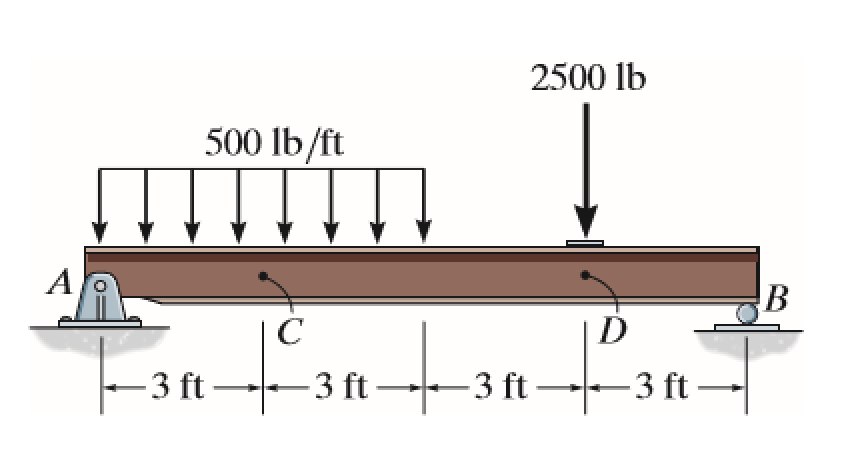
As illustrated above, a simple supported beam with a pin support at point A and roller at point B
experiences both a distributed loading and external force. The problem specifically asks for internal
forces and moments at C and D; however, the module shows forces and moments at all points of the beam.
Determining support the reactions at A and B, it can be found that there exists no force in the
x-direction. Thus, internally, the beam experiences no normal force.
Using method of sections, shear and moment equations can be found for a particular section varying
with the chosen position along the beam (where x = 0 is at point A). The following module calculates
and graphs shear and moment, and allows for the magnitude and location of the external force and load
to be changed.
Moving Downward or Upward
The following module solves the friction problem 8-88 of the 13th edition of Statics by R.C. Hibbeler.
Two blocks, M on the slope and W hanged, are connected by rope crossing through a drum. The slope has
an inclination of angle $\theta$, the coefficient of static friction between M and slope is $\mu_1$,
and that between rope and drum is $\mu_2$. Try to determine the critical values of W which lead to the
break of equilibrium under different conditions, and compare with the given solution. Note that two
critical values of W are involved which cause W move up or move down separately.
Stress on Oblique Plane
This module is designed to show the stresses on an oblique plane with inclined angle $\theta$ under
axial loading.
Consider a rectangular bar with constant cross section shown below, which is subjected to the axial
force P. Now, consider an oblique plane that passes through the bar and is inclined at the angle
$\theta$ relative to the vertical axis. What will be the forces and stresses acting on this oblique
plane? We will follow the following three steps in addressing this question.
Step 1: Using the method of sections we determine that the force acting on the inclined plane should
be
P to ensure horizontal equilibrium.
Step 2: We resolve P into two components, normal force N which is perpendicular to the inclined plane
and shear force V which is parallel to the inclined plane.
Step 3: We use the definition of the normal and shear stress, $\sigma$ = $\frac{N}{A_{\theta}}$ and
$\tau$ = $\frac{V}{A_{\theta}}$, to calculate these stresses noting that the area of the inclined
plane
is related to the area perpendicular to the x-axis by $A_{\theta}$ = $\frac{A_{0}}{cos\theta}$.
Stress at a Point
The following module demonstrate the concept of stress at a point.
Consider a body applied with traction (or displacement) on the boundary. To investigate the stress of a point inside, cut the body with a plane. Without losing generality, choose the plane perpendicular to z-axis. Consider a small area on the plane with size $\Delta$$A_z$, acted with a force $\Delta$$F_z$ which has components of $\Delta$$F_{zx}$, $\Delta$$F_{zy}$, $\Delta$$F_{zz}$. Then the stresses can be defined as
\begin{equation}
\tau_{zx} = lim_{\Delta A_{z} \rightarrow 0} \:\: \frac{\Delta F_{zx}}{\Delta A_{z}}
\end{equation}
\begin{equation}
\tau_{zy} = lim_{\Delta A_{z} \rightarrow 0} \:\: \frac{\Delta F_{zy}}{\Delta A_{z}}
\end{equation}
\begin{equation}
\sigma_{zz} = lim_{\Delta A_{z} \rightarrow 0} \:\: \frac{\Delta F_{zz}}{\Delta A_{z}}
\end{equation}
The general state of stress at this point can be obtained if we take a stress cube out and look at the stress at the remaining surfaces.
Strain
This module presents the definition of strain.
Strains are measures of deformation represented by displacements between particles in the body
relative
to a reference configuration. They are classified as either normal or shear. Normal strains represent
changes in lengths of line elements oriented along the three axes associated with an infinitesimal
cube
and hence are perpendicular to the cube's faces. Therefore they also represent volumetric changes.
Shear
strains represent changes in the angles of mutually orthogonal line elements in the three planes x-y,
y-z and x-z of an infinitesimal cube. Therefore they also represent cube's distortion.
There are three normal strains and six shear strains, but only three of the six shear strains are
independent because shear strains are symmetric. These strains comprise the three-dimensional strain
tensor in analogy with the stress tensor and may be represented using the same matrix notation.
Tensile Test
The strength of a material depends on its ability to sustain a load without undue deformation or
failure. This property is inherent in the material itself and must be determined by
$\textbf{experiment}$. One of the most important tests to perform in this regard is the
$\textbf{tensile test}$. It is primarily to determine the relationship between the average $\textbf{normal stress}$ and
average $\textbf{normal strain}$.
We can determine the nominal or engineering stress by dividing the applied load P by the specimen's
original cross-sectional area $A_{0}$. This calculation assumes that the stress is constant over the
cross section and throughout the gauge length. We have
\begin{equation}
\sigma = \frac{p}{A_{0}}
\end{equation}
Likewise, the nominal or engineering strain is found directly from the strain gauge reading, or by
dividing the change in the specimen's gauge length, $\delta$ , by the specimen's original gauge length
$L_{0}$. Here the strain is assumed to be constant throughout the region between the gauge points.
Thus
\begin{equation}
\epsilon = \frac{\delta}{L_{0}}
\end{equation}
If the corresponding values of $\sigma$ and $\epsilon$ are plotted so that the vertical axis is the
stress and the horizontal axis is the strain, the resulting curve is called a $\textbf{conventional}$
stress-strain diagram.
Internal Shear and Moment Diagram
The following module expands on the topic of two-dimensional FBD diagrams, the method of sections, and internal forces and moments covered previously in Statics. The module illustrates homework problem 16 in chapter 1 of the 10th edition of Hibbeler's Mechanics of Materials.
As illustrated above, a supported beam has two pin supports: one at point A and one at point B. Although different from the typical beam setup of one roller and one pin, the internal normal force is not affected. Solving for the support reactions at A and B, it is found that the two exert a horizontal reaction force. Since there is not horizontal external force or loading, the internal forces in the horizontal direction is neglected. Additionally the textbook problem assumes the reaction supports are vertical.
The problem itself asks for internal forces and moments at D and E; however, the module shows forces and moments at all points of the beam. Using method of sections, shear and moment equations can be found for a particular section varying with the chosen position along the beam (where x = 0 is at point A). The shape of the distributed loading must be noted. A common rectangular distributed loading would produce a shear diagram of the first order (linear) and thus a moment diagram of the second order (quadratic). Since this shape is that of a triangle, the shear now becomes a second order function.
The following module calculates and graphs shear and moment, and allows for the magnitude of the distributed loading peak, location of the peak and the location of support reaction B to be changed.
Pin Diameter Determination
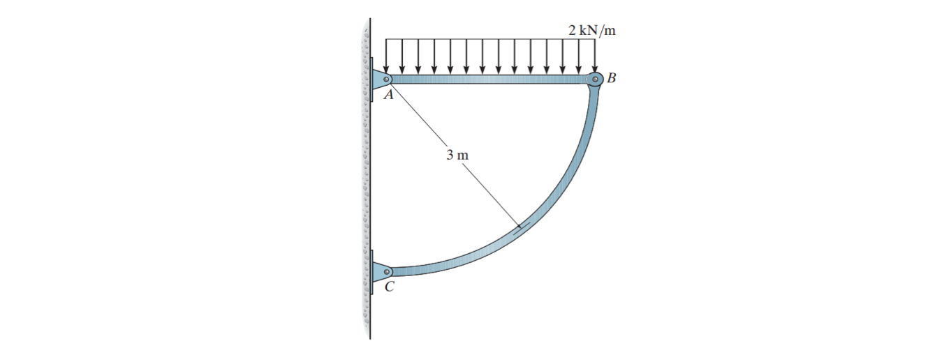
The following module aims at solving homework problem 1-81 in Strength of Material. Problem 1-81 asks for the required diameter of the pins at A and B given that the allowable shear stress for the material is $\tau_{allow}$ = 100 MPa. Both pins are subjected to double shear. Two types of force distributions are allowed to be chosen, equally distributed and triangularly distributed. The radius of arc BC is set to be same as the member AB, i.e. frame ABC is a quarter circle. The magnitude and position of load is changeable. Free body diagrams of member AB and Pin A are shown on the side.
Mechanical Properties of Materials
Mechanical Properties of Materials - Chapter 3.1 to 3.4
The first diagram depicts the control force bar. The second second depicts how length affects the
total
change in length when a force is applied. The third diagram depicts how a change in area affects the
total change in length when a force is applied.
The first graph shows the three diagrams of when a force is applied. The equation is $\delta$l =
$\frac{Fl}{AE}$
The second graph depicts $\sigma$ = Ee.
Stress-Strain Relations
This module is a slight modification of the module "Cauchy And Engineering Strain Deformation In 3D"
available on the Mathematica Demonstrations website.
This module demonstrates the deformations and strains that arise in an infinitesimal cubical element
of
a material due to the application of single or combined stresses. The stresses applied cause a
deformation of the cube that depend on the magnitude of the material properties (Young's Modulus: E
and
Poisson's Ratio: v). All stresses and resulting strains are shown in tensorial form below on the left
side of the box, while the deformation of the cube is shown on the right.
Adjust the sliders to change the stress components applied to the cube. The "reset view" button
returns
the cube to its default orientation. The "reset stress" button returns all stresses to zero. You can
rotate the view of the cube by clicking and dragging on the cube. The matrices represent the stress
and
strain tensor components acting on the cube. The controls at the bottom adjust the view of the cube.
Positive stresses indicate tension and the resulting positive strains are elongation.
Principles of Stress Superposition
This module is designed to demonstrate the superposition of deformation or strain of a cube in 3D.
The principle of superposition is often used to determine the stress, strain or displacement of a
point in a cube when the cube is subjected to a complicated loading. By subdividing the loading into
components, the principle of superposition states that the resultant stress, strain or displacement at
a point can be determined by algebraically summing the stress, strain or displacement caused by each
component applied separately to the cube.
In the present module, complex stress loading can be applied on the cube. However, the stress can be
divided into six components, and we can calculate the strain of cube under each stress component. Then
the total strain will be the sum of these six strain.
This principle will be used whenever the Hooke's law applies, which means there is a linear relation
between stress and strain. Also, the small deformation assumption needs to be hold as a prerequisite,
which means the loading must not significantly change the original geometry or configuration of the
member. In order to see the deformation clearly, we set a variable "deformation scaling" to enlarge
the deformation shown on the figure while do not change the actual strain value.
Thermal Stress
A change in temperature can cause a body to change its dimensions. For homogeneous and isotropic
materials with its expansion or contraction linearly related to the temperature increase or decrease,
the displacement can be calculated using the formula $\delta_{T}$ = $\alpha\Delta TL$, where
$\delta_{T}$ is the algebraic change in length, $\alpha$ is the linear coefficient of thermal
expansion, $\Delta$T is the algebraic change in temperature and L is the original length.
In the present case, a member with original length $L_{0}$ is fixed on the left and free on the right,
with a distance $\Delta_{0}$ to the right wall. When temperature is increased, the end on the right
will expand, but no thermal stress will be produced until its reaches the wall. After touching with
the wall, and continuously increase the temperature, then thermal stress will be produced. Think about
how to calculate the thermal stress, and click on "Superposition" and "Calculation" for checking.
Torsion
Consider a shaft to be rigidly attached at one end and twisted at the other end by a torque
$\textbf{T}$, which is applied perpendicular to the axis of the shaft. Such a shaft is said to be in
torsion.
For a solid shaft subject to a torque $\textbf{T}$, the torsional shearing stress, $\textbf{$\tau$}$,
at a distance, $\textbf{$\rho$}$, from the center of the shaft is
\begin{equation}
\tau = \frac{T\rho}{J}
\end{equation}
\begin{equation}
\tau_{max} = \frac{Tr}{J}
\end{equation}
where J is the polar moment of inertia of the section and r is the outer radius.
The angle $\Phi$ through which the shaft length $\textbf{L}$ will twist is
\begin{equation}
\Phi = \frac{TL}{JG}
\end{equation}
where $\textbf{G}$ is the shear modulus of the shaft.
Shear Stress from Torque
The following module discusses the topics of shear stress from applied torques and the angle of twist. The module illustrates homework problem 9 in chapter 5 of the 10th edition of Hibbeler's Mechanics of Materials.
As illustrated above, a cylindrical rod is subjected to two torques of varying direction and torque. The problem specifically asks for the shear stresses at points A and B. Please note that while point A lies on the outside surface of the rod, point B lies 20 mm from the center of the shaft. Similar to normal stresses and beams under transverse loads, torque problems require the computation of the internal torque to find the stresses at the desired area. The module follows the sign convention outlined in Hibbeler (pg. 209 of the 10th edition).
\begin{equation}
\tau = \frac{T \rho}{J}
\end{equation}
\begin{equation}
\tau_{max} = \frac{T r}{J}
\end{equation}
In addition to shear stress, the angle of twist has been included as a feature. To calculate the angle of twist at an end of a rod that is subject to multiple torques, the angle of twist formula will be applied to each section of uniform torque and then added up to get the total angle of twist. Again, this runs analogous to the calculations of deformations in beams. While the length of the beam was not given in the problem, an arbitrary range of 0 to 1 m has been given.
\begin{equation}
\phi = \frac{TL}{JG}
\end{equation}
The following module allows for the magnitude and position of the two applied torques to be changed along with the radius, length, and shear modulus (G). It calculates the shear stress at a certain position that can be changed longitudinally (x-axis) and radially as well as the angle of twist. The mesh and volume element may be viewed. Note that although the red section point may be rotated about the x-axis, this does not change the value of the internal shear stress value. Only translating the point radially on the yz plane will affect the shear stress.
Stress on Over-Constrained Bar
Consider two shafts bounded by two rigid walls. A uniform force or torque is applied on the interface between two shafts, and thus results in an axial deformation or twisting of shafts. When force is applied, equation E = $\frac{\sigma}{\epsilon}$ is used to solve for reaction force applied from walls to shafts, where E is the young's modulus, $\sigma$ is the stress, $\epsilon$ is the strain. Since the summation of deformation of two shafts must be 0 (as two walls are rigid), $\epsilon_{Left}$ + $\epsilon_{Right}$ = 0. Also, the summation of two reaction forces from walls must equals to F, the force applied, since the system is in equilibrium condition.
Solving these two equations simultaneously gives the numerical solution of two reaction forces, $F_1$ and $F_2$.
Similar procedure can be taken to solve for the torques applied from walls to shafts when a torque is applied to the interface between two shafts. Equation $\varphi$ = $\frac{TL}{GJ}$ and T = $T_1$ + $T_2$ are used instead, where $\varphi$ is the twisting angle of the shaft, T is the torque, L is the length, G is the shear modulus, J is the polar moment of inertia of the cross section area.
Bending
The following module demonstrates the deformation of a bar section caused by pure bending moment.
Consider a section of bar with square cross section that is marked with longitudinal and transverse grid lines. When a pure bending moment is applied, the bar will deform in a way shown in the following module. The neutral plane or neutral axis will not undergo any deformation in the longitudinal direction. When a positive moment is applied, the longitudinal line above the neutral axis and below the neutral axis will undergo a extension and compression separately, vice versa for a negative moment. The transverse line which is originally vertical to the neutral axis will keep to be vertical after deformation.
Shear Flow of a Section
Shear stress in a member can be determined with shear formula, $\tau = \frac{VQ}{It}$, where V is the shear force applied on the section, Q = y̅'A', where A' is the area of the top (or bottom) portion of the member's cross section, above (or below) the section plane where t is measured, and y̅' is the distance from the neutral axis to the centroid of A', I is the moment of inertia of the entire cross section, t is the thickness of the cross section at the point where tau is measured.
In this module, four composite sections are presented with height, width, and thickness changeable. For the first three sections, thickness is assumed to be uniform. For the hollow circle, height is the outer diameter and thickness is the inner diameter. For each of them, shear force V is assumed to be applied to the negative y direction, i.g. downward, on the whole cross-section simultaneously. With the red A-A plane moving either horizontally or vertically, the distribution of shear stress $\tau_{xz}$ will be plotted.
Combined Loadings
The solid rod shown below is fixed on the wall at one end and applied with a force at the other end.
The module is designed to show how to determine the internal loading and stress on a chosen section A.
Stress Transformation
This module is revised on the basis of the prototype developed by Nick Bongiardina et al to show the
idea of stress transformation as well as Mohr's Circle for plane stress problem.
The state of plane stress at a point is uniquely represented by two normal stress components and one
shear stress component acting on an element. These three component will be different for each specific
orientation $\theta$ of the element at the point. Specifically, if the stress state for a given
element is known, with the two normal stresses and one shear stress represented by $\sigma_{x}$,
$\sigma_{y}$ and $\tau_{xy}$; after a rotation of an angle $\theta$, the stresses change to
$\sigma_{x^{'}}$, $\sigma_{y^{'}}$ and $\tau_{x^{'}y^{'}}$, and the relations between these two sets
of stress, or stress transformation equation can be written as
\begin{equation}
\sigma_{x^{'}} = \frac{\sigma_{x} + \sigma_{y}}{2} + \frac{\sigma_{x} - \sigma_{y}}{2}\cos(2\theta) +
\tau_{xy}\sin(2\theta)
\end{equation}
\begin{equation}
\sigma_{y^{'}} = \frac{\sigma_{x} + \sigma_{y}}{2} - \frac{\sigma_{x} - \sigma_{y}}{2}\cos(2\theta) -
\tau_{xy}\sin(2\theta)
\end{equation}
\begin{equation}
\tau_{x^{'}y^{'}} = - \frac{\sigma_{x} - \sigma_{y}}{2}\sin(2\theta) + \tau_{xy}\cos(2\theta)
\end{equation}
After eliminate the parameter $\theta$ we can get the following equation
\begin{equation}
(\sigma_{x^{'}}- \frac{\sigma_{x} + \sigma_{y}}{2})^{2} + (\tau_{x^{'}y^{'}})^{2} = (\frac{\sigma_{x}
- \sigma_{y}}{2})^{2} + (\tau_{xy})^{2}
\end{equation}
Which is the equation of Mohr's Circle for plane stress problem. Once we set the stress of
$\sigma_{x}$, $\sigma_{y}$ and $\tau_{xy}$ at 0 degree, the Mohr's Circle can be drawn in the
$\sigma_{x^{'}}$ - $\tau_{x^{'}y^{'}}$ plane, and the point represent 0 degree can be determined.
Then, according to the stress transformation equation, we can easily determine the stress for the same
element with an orientation of angle $\theta$.
The following module is used to show such process. Give the stress at 0 degree first, and then give
the orientation angle $\theta$, see how the stress of the element change. Also see the stress plot for
the whole range of orientation.
Beam Deflection
The module below shows how to determine the deflection of a beam. Two types of beam with two types of
cross sections are available. As an intermediate step, the internal force diagram is also provided for
the final determination of the deflection.